

![[Electronics/DIY] Renovating 60's Radio Turntable](https://images.squarespace-cdn.com/content/v1/5aca3b7ab10598283d220390/1602420333666-HVXI7H6TDOBST6M53HEE/IMG_20200420_095511.jpg)
[Electronics/DIY] Renovating 60's Radio Turntable
It all started with an advertisement on a famous social network about an old radio and vinyl player whose destiny was to finish to the trash. Back in time, I was working on a smart speaker with an e-ink screen based on raspberry pi and I directly thought that this old radio would be perfect to make this project a reality.
It all started with an advertisement on a famous social network about an old radio and vinyl player whose destiny was to finish to the trash. Back in time, I was working on a smart speaker with an e-ink screen based on raspberry pi and I directly thought that this old radio would be perfect to make this project a reality.
Without hesitation, I contacted the owner and a few days later I had this dusty radio at home. My main plan was to put my smart speaker system to replace the radio and connect it to the already existing speaker.

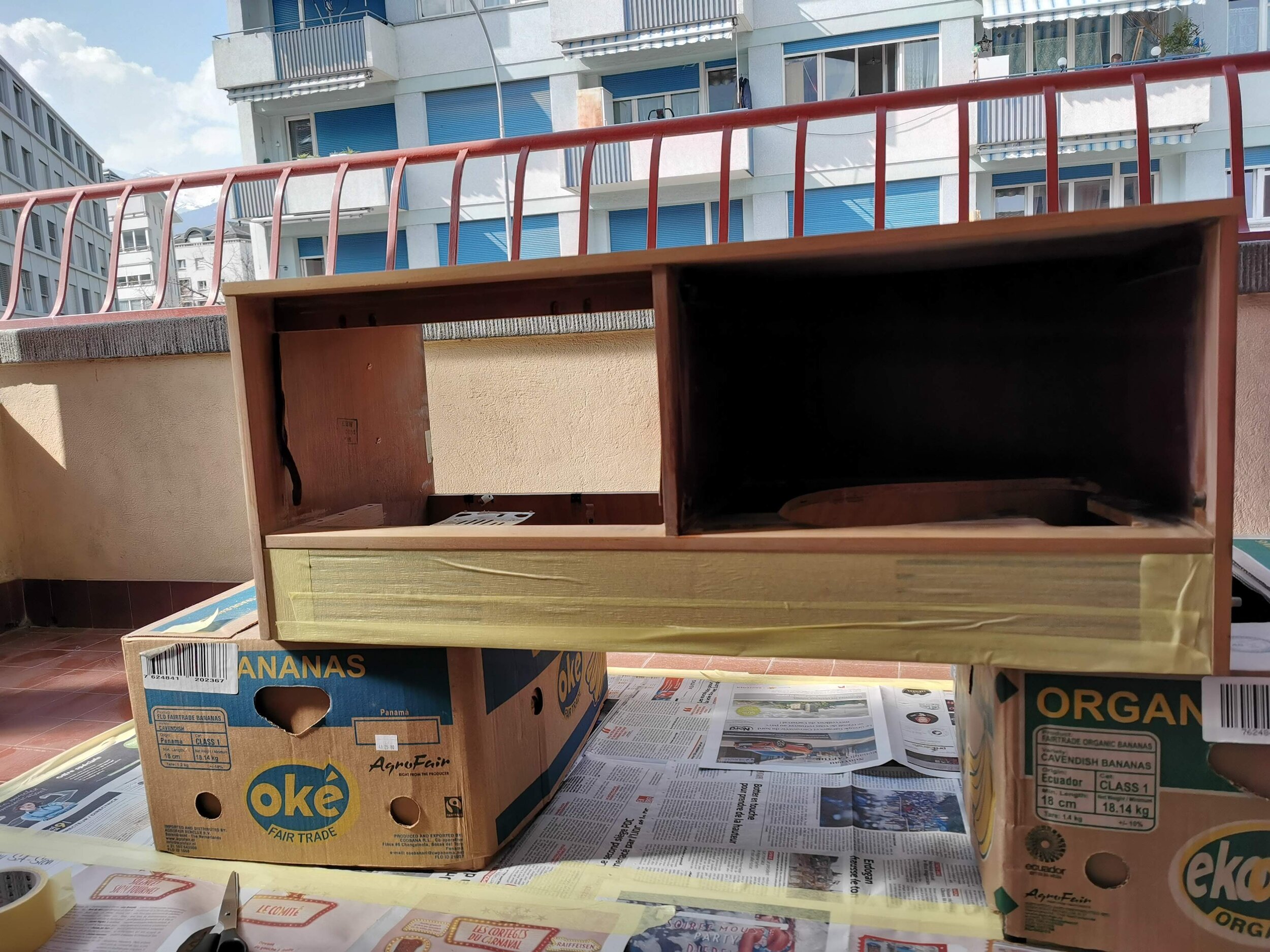
The first step is to open up everything and get rid of the stuff I won’t need. It may hurt all the old electronic lovers and it did hurt me too to destroy this radio since it was still working., but it is not my thing to listen to the only noisy AM Italian radio channel I found.
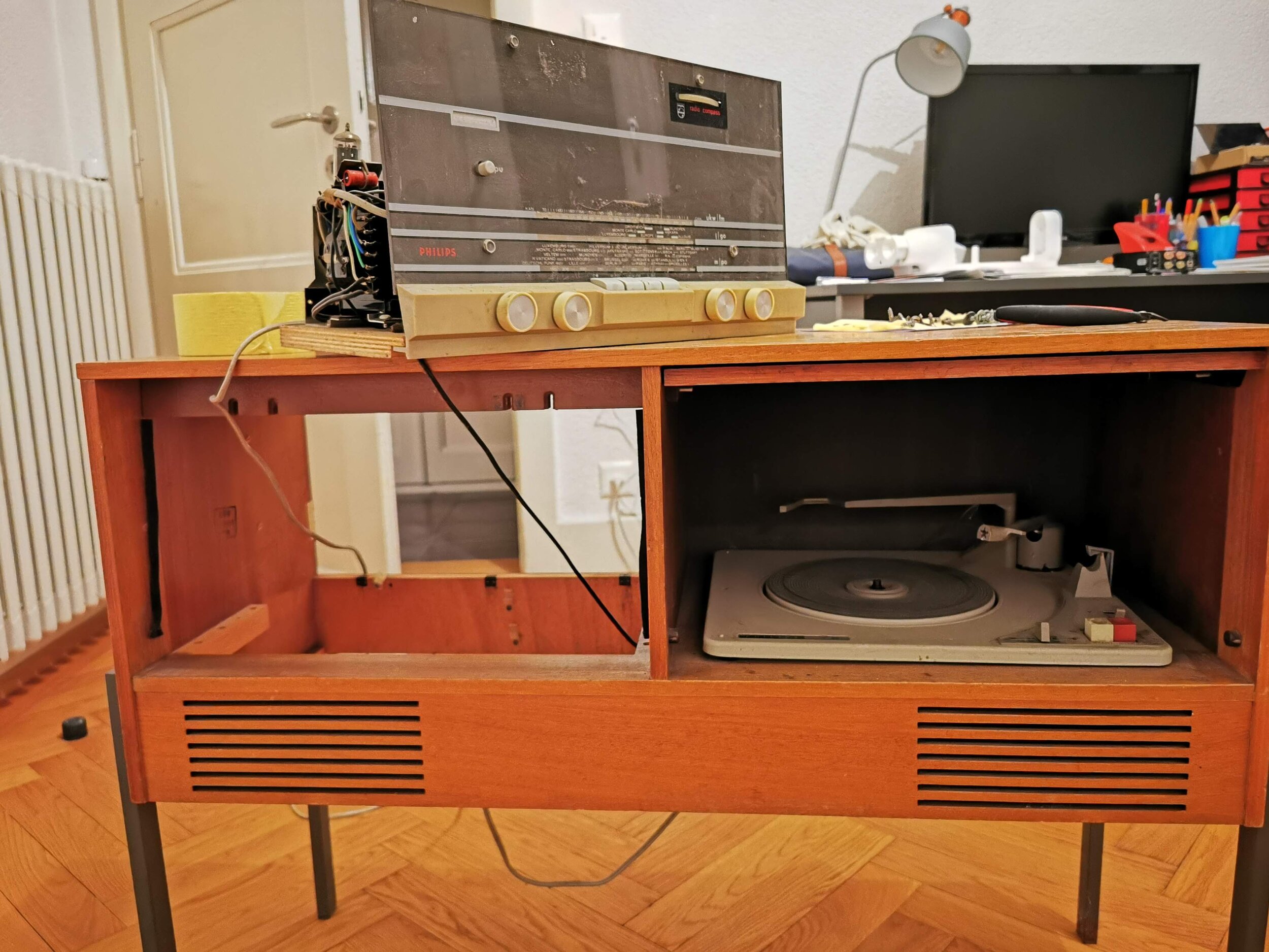
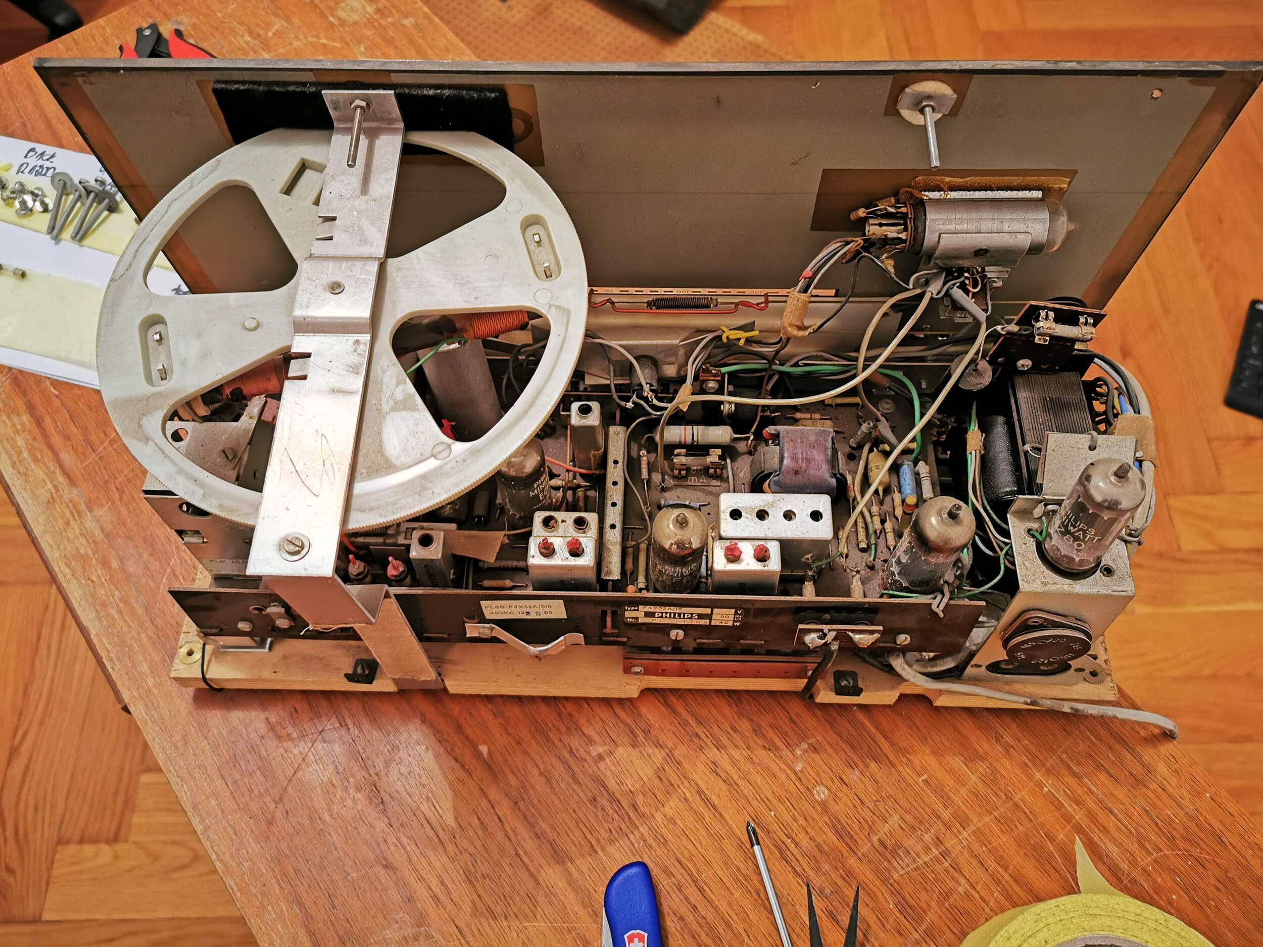
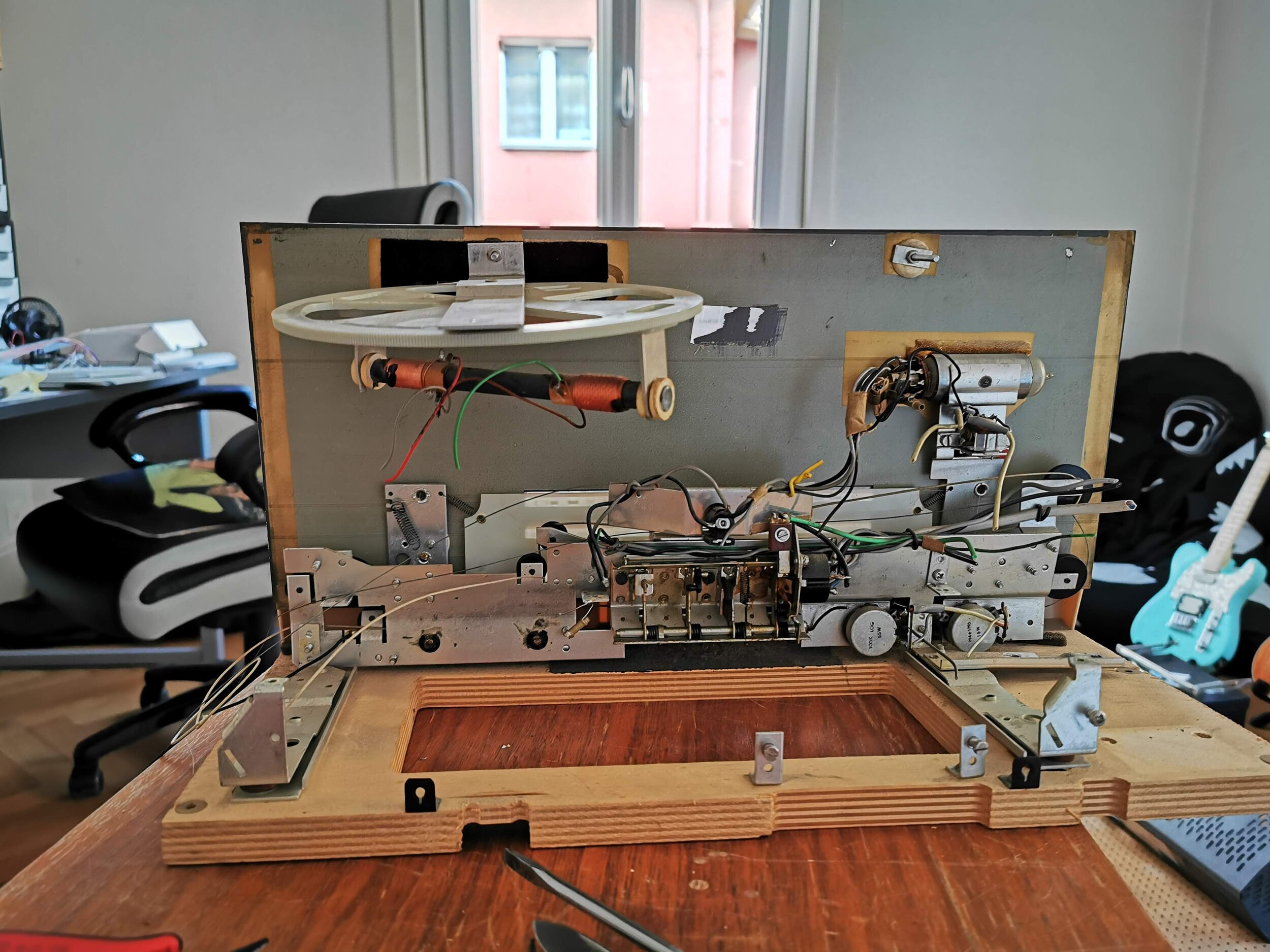
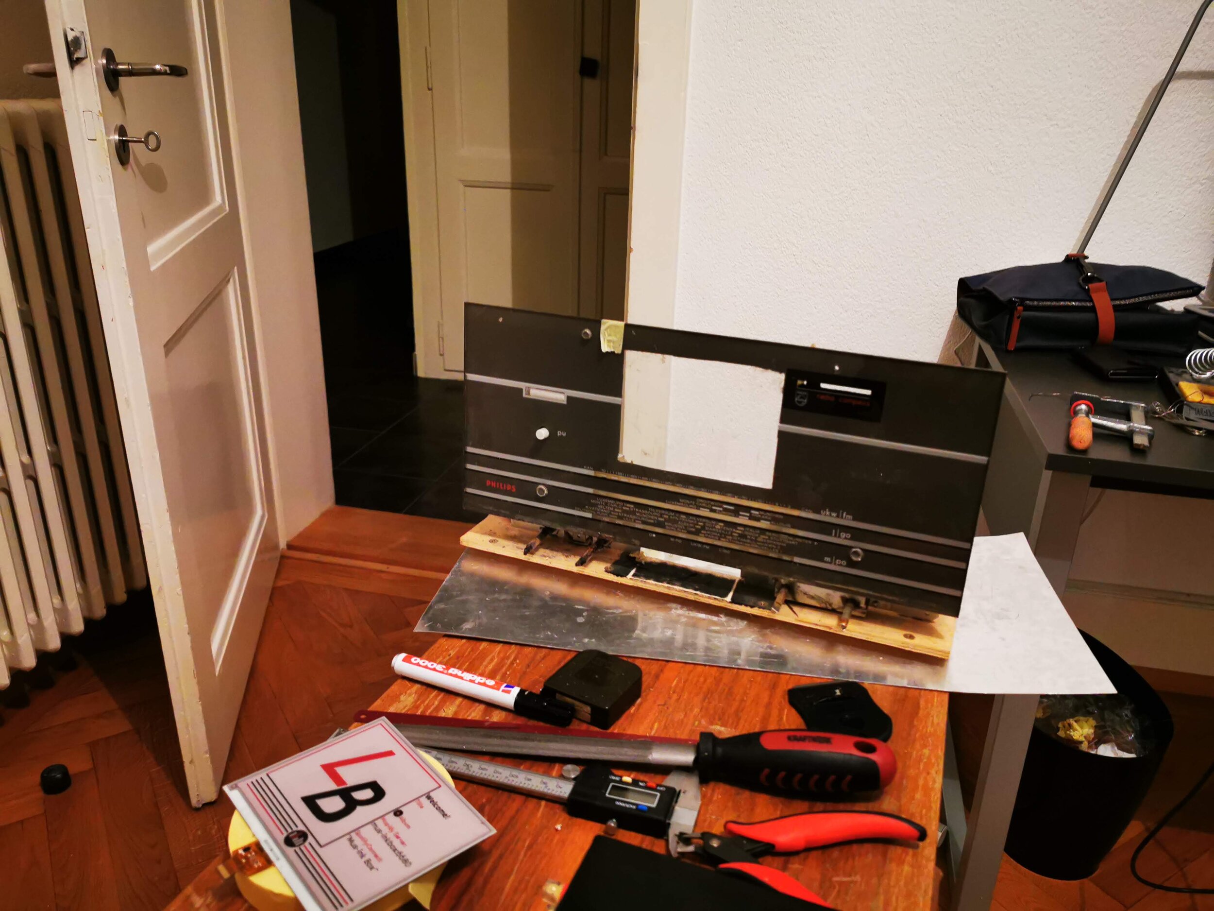
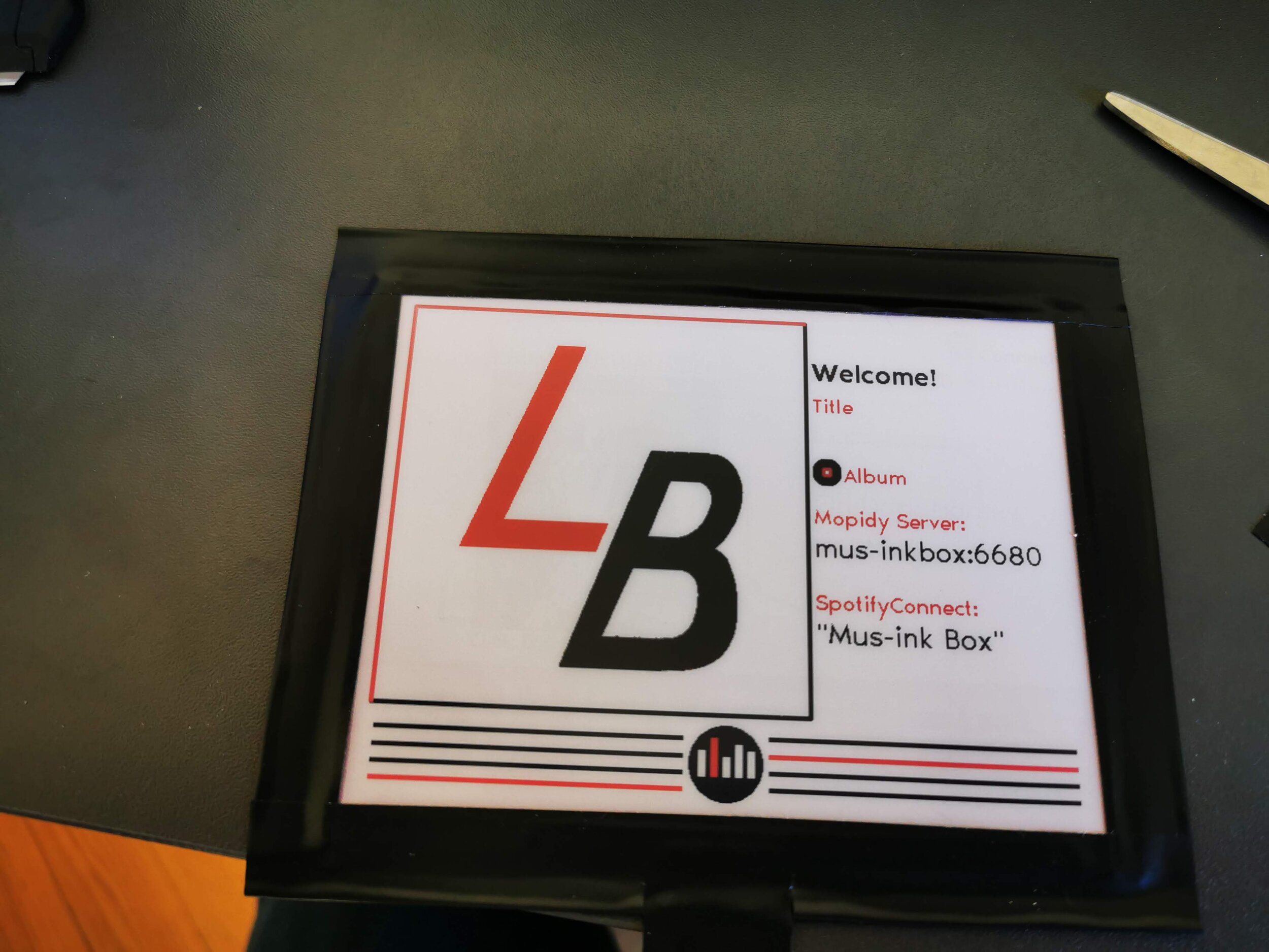
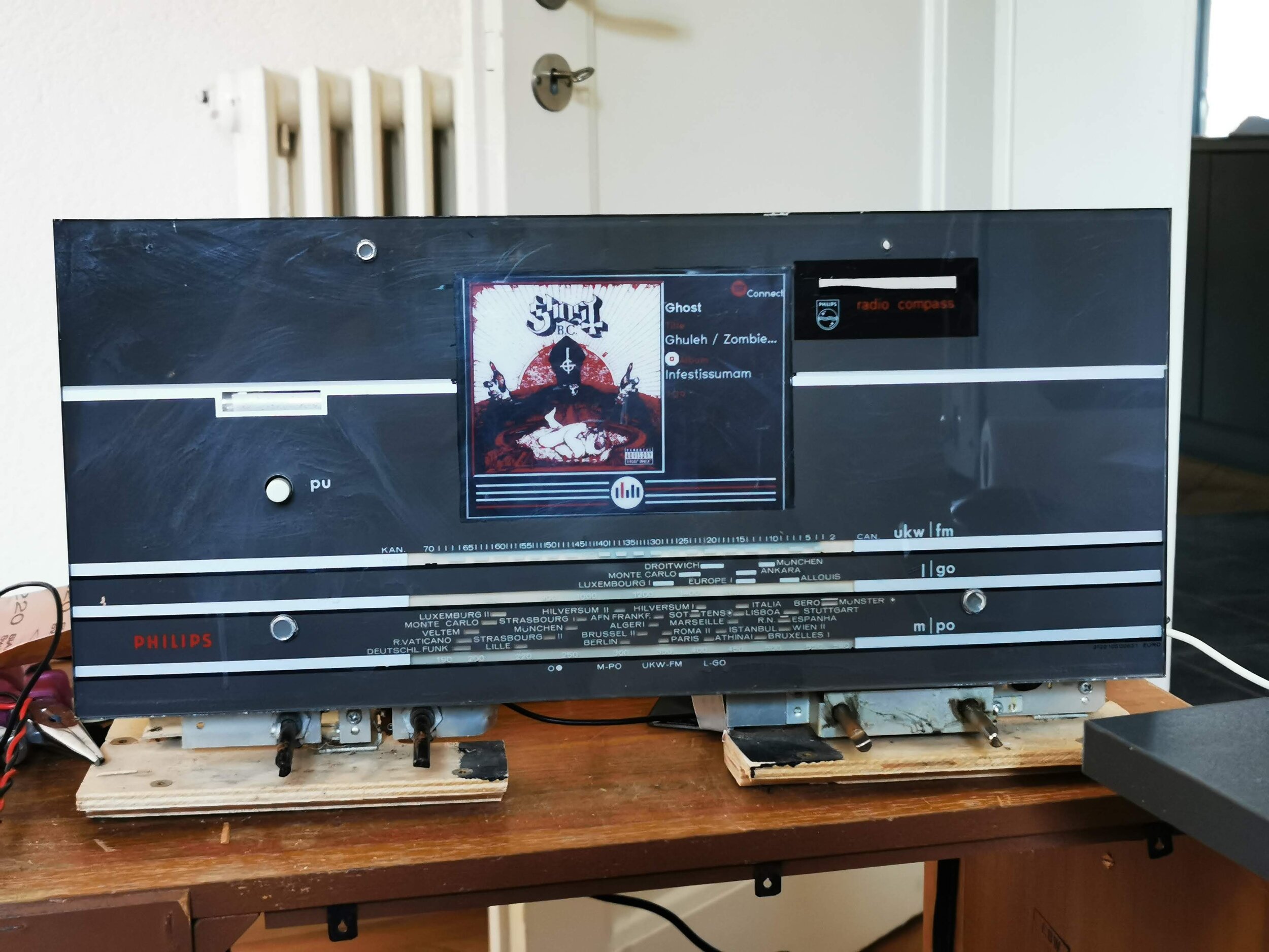
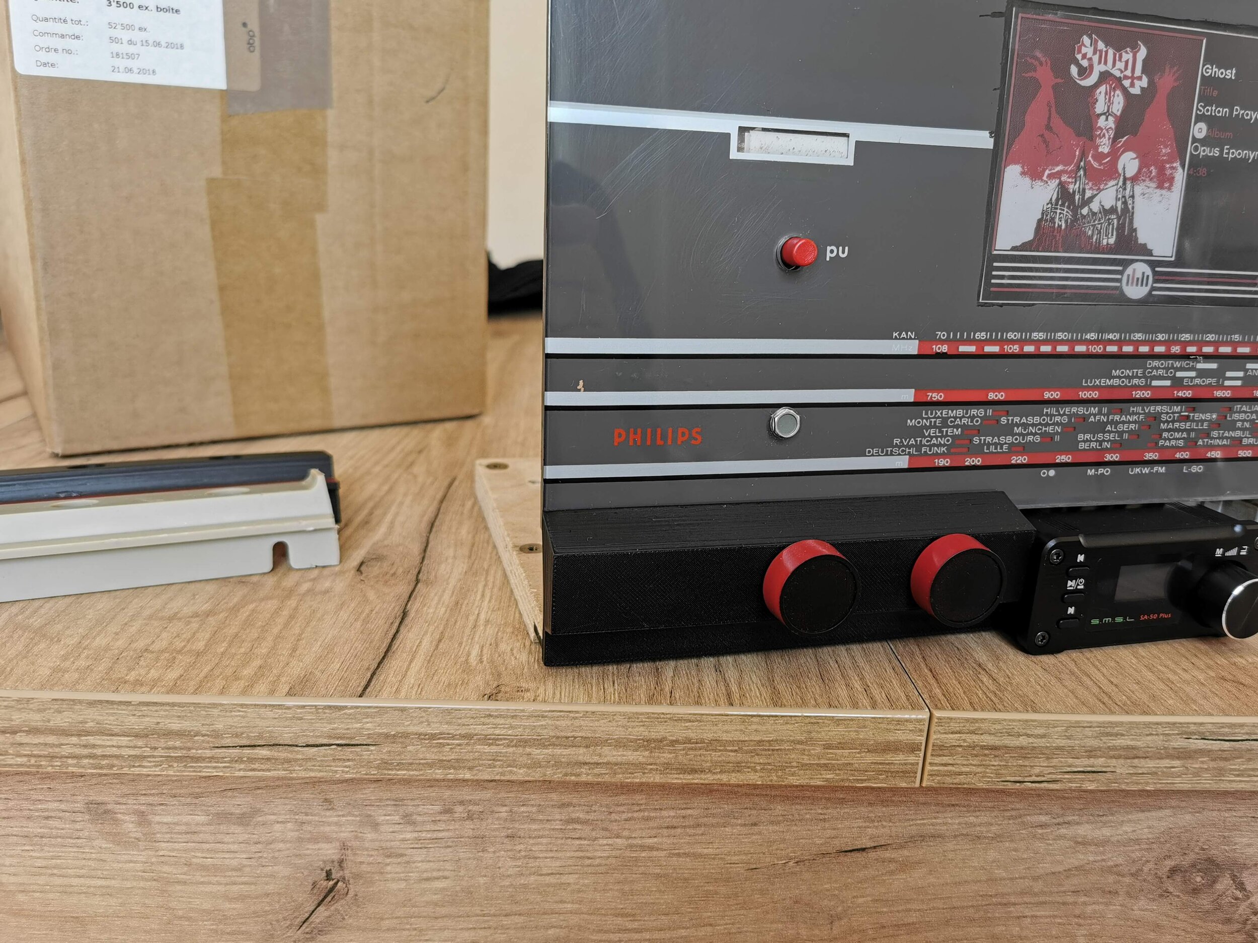
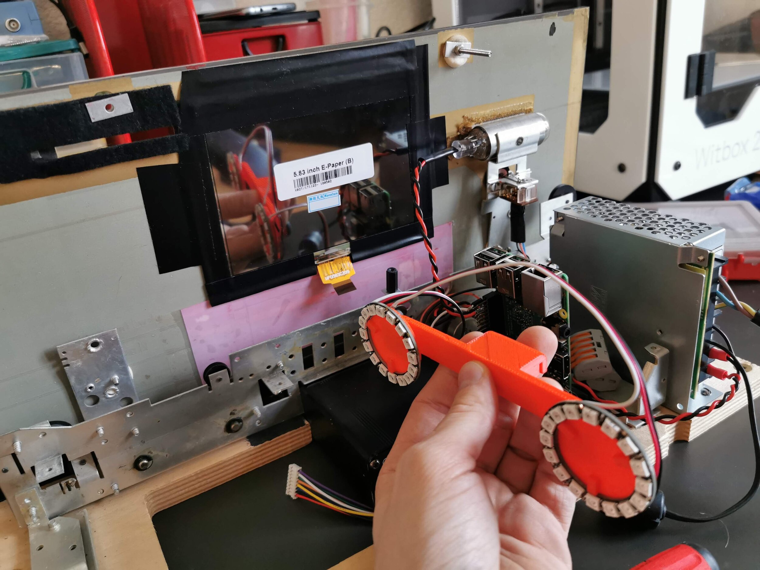
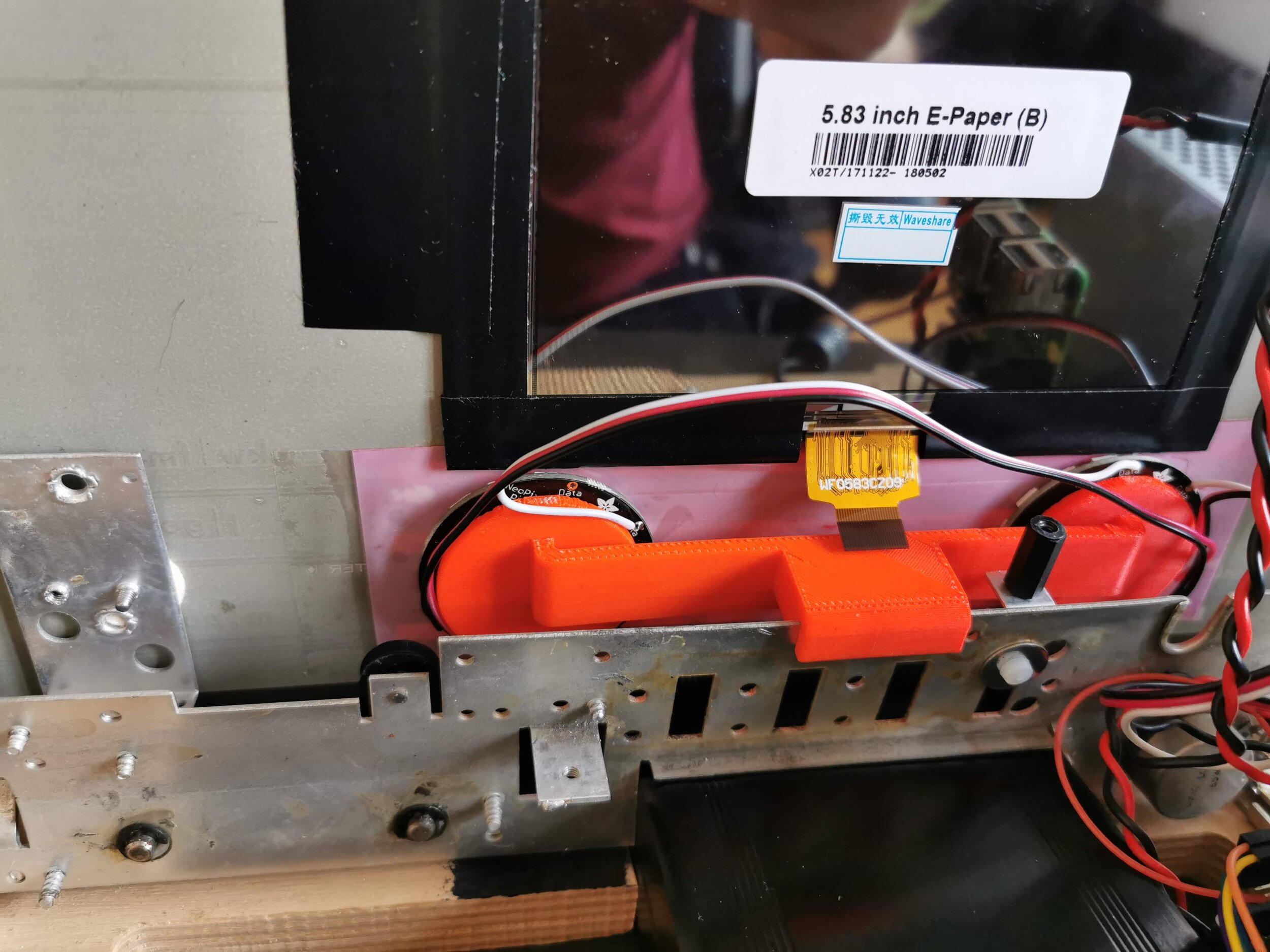
Time to open this old radio and remove its electronic. With the help of a sharp razor blade, I removed the paint on the glass to have some space to put my e-ink display. I chose a 5.83 e-ink by waveshare with 3 colors: black, white, and red. More info about the display here.
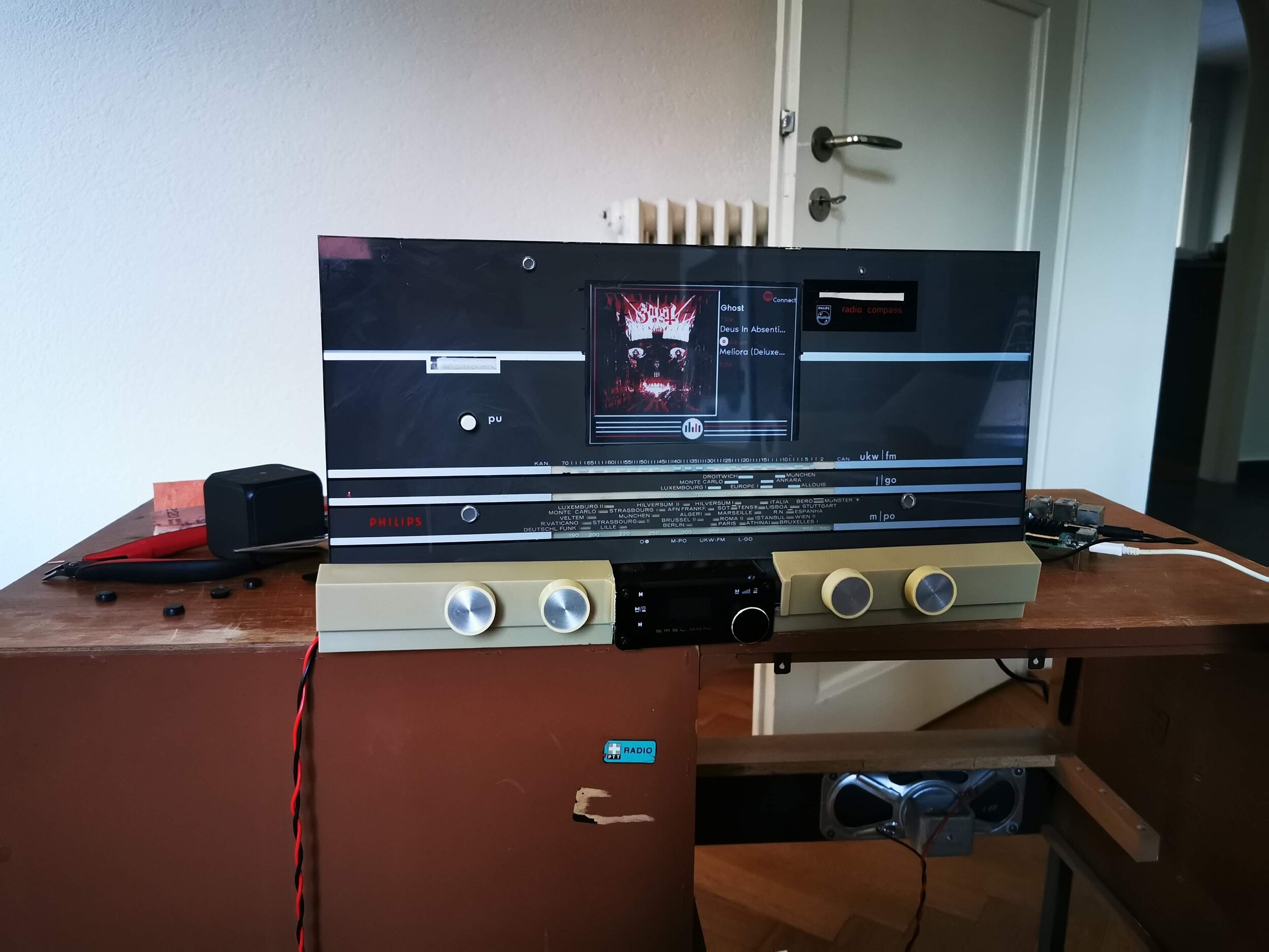
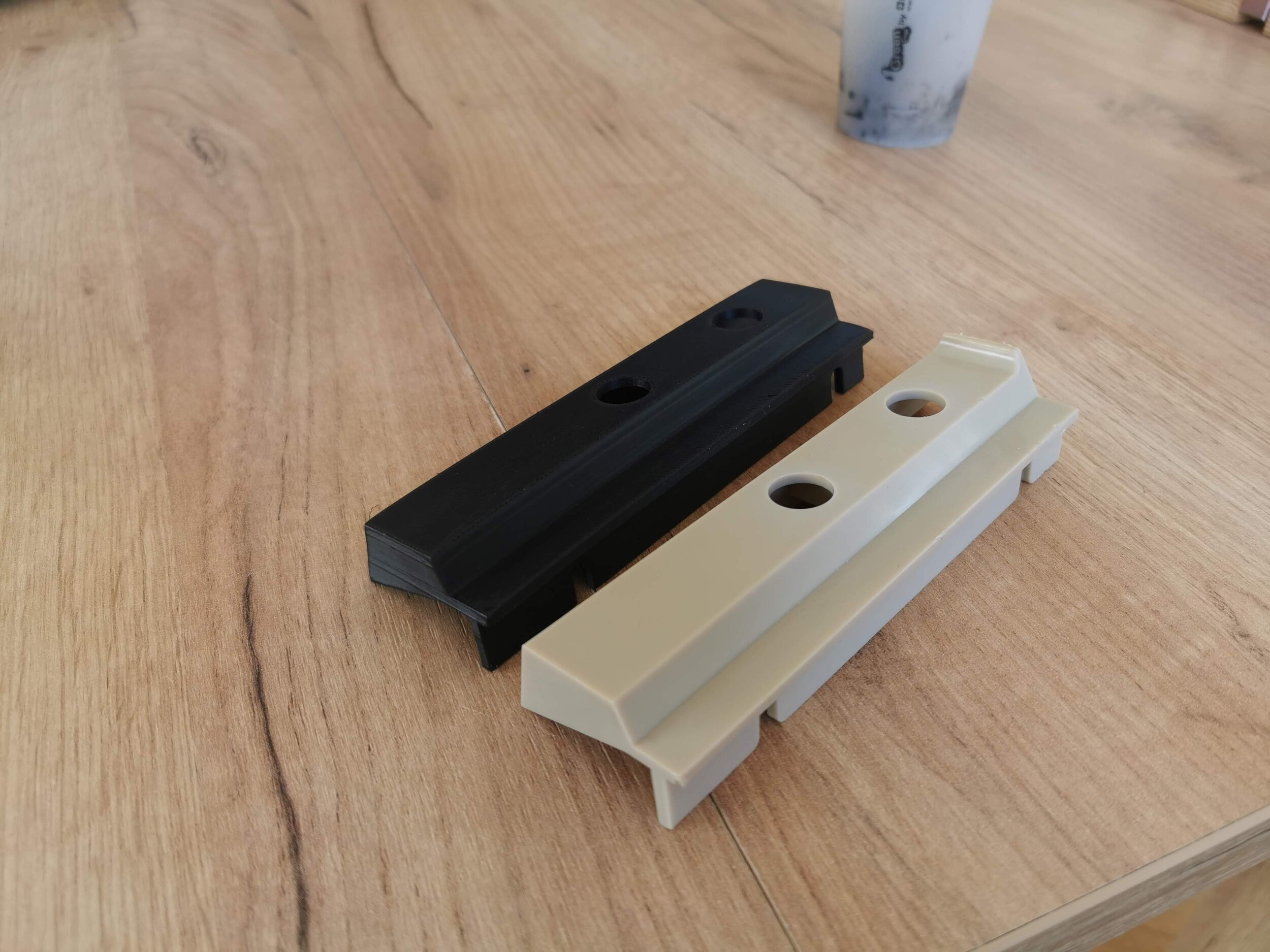
With that done, I removed the old mechanical buttons of the radio to put a cheap amplifier found on amazon. My goal here is not to make a high quality audio system but to make a nice looking furniture that can stream some audio with Spotify for example. When adding this little amp, I had to cut down the bottom plastic piece that was holding the button and yeah, I messed up the cut… But having a 3d printer, after a few measurements, I 3d-printed the pieces directly the right size and they fit perfectly around the buttons.
To make the system a bit more interactive, I added some neopixel rings that act like vumeters. Some nice 3d printed pieces hold them well to the whole system. With all the electronic wired up, it was time to print everything.
With all that done, it was time to sand all the wooden parts of the radio and pass some paint on it. I decided to go for a black finish and to let some parts all natural giving a nice industrial look to it. I also cleaned and painted all the buttons in black and red to fit the e-ink display colors. Here we are with the final result!
For more details on the software part, everything is documented on my GitHub, you just have to follow this link. As a quick resume, I added mopidy and librespot to have Spotify access. With the mopidy api I retrieve the album artwork and process a k-mean clustering to decompose it in 3 colors for the e-ink display. With a loopback audio card made with pulseaudio, I do a fft of the actual music playing and display it on the neopixels ring. Finally, everything is customizable and can be easily modified with a properties file.
[Electronics] Nanopi A64 and the GPIO

Recently I “found” some Nanopi A64 (micro computer made by FriendlyARM similar to Raspberry Pi) that were unused. After some research, I found the official wiki and decided to try them out! My first step was to install an OS, I tried the two OS proposed by FriendlyARM which are Ubuntu-Core and Ubuntu-Mate (Mate has an UI).
And success, they boot and those OSs seems working pretty find! So naively I thought: “Cool I’ve two little electronic circuits that I can use as Raspberry Pi and I got them for free!”. At this point, I want to try to access the GPIO and try to install the common GPIO library for Raspberry PI since on the wiki I found “GPIO pin-header compatible with Raspberry Pi “ . Long story short didn’t work at all. After some research on internet, FriendlyARM doesn’t provide any GPIO support for the Nanopi A64 and I never found anybody working with the GPIO on this board…
At this point, I thought that GPIO on this board couldn’t be accessible. After some research, I found a thread on Armbian forum called Build libgpiod the "New GPIO Interface for User Space" . I gave a look and it’s talking about Nanopi and a library called libgpiod . So time to give it at try! Let’s install this lib on our Ubuntu-Core or Ubuntu-Mate! Again, didn’t work either…
This reference about libgpiod and Nanopi was on Armbian forum so now my guess is to have an Armbian that work for Nanopi A64! Guess what, it’s not officially supported.. but after some research I found that on the same forum: [Experiment] armbian on NanoPi A64 . Apparently, some people succeded to install Armbian on Nanopi A64 and there is a description of the few tricks to do it!
So it was time to clone the Armbian Git and try to compile an Armbian for my Nanopi A64! And guess what, it worked! For the people that want to do it too, I’ll resume the manipulation that I made according to the “guidol” (all credits to him for this part!) modification to do it:
After cloning the Armbian build git, create an new configuration for the nanopia64 in ./build/config/boards/nanopia64.conf
# A64 quad core 512MB-2GB SoC GBE
BOARD_NAME="NanoPiA64"
BOARDFAMILY="sun50iw1"
BOOTCONFIG_DEFAULT="sun50iw1p1_config"
BOOTCONFIG="nanopi_a64_defconfig"
#
MODULES="sunxi_codec sunxi_i2s sunxi_sndcodec 8723bs"
MODULES_NEXT=""
#
KERNEL_TARGET="default,next,dev"
CLI_TARGET="bionic,stretch:next"
DESKTOP_TARGET="xenial:default"
#
CLI_BETA_TARGET=""
DESKTOP_BETA_TARGET=""
Then compile Armbian with ./compile.sh EXPERT="yes" and select Nanopi A64 for the platform. In my case I also selected DEV for linux kernel. My result is then: Arbian_5.78_Nanopia64_Debian_stretch_dev_5.0.7.img (guidol was Armbian_5.71_Nanopia64_Debian_stretch_dev_4.20.0 )
This image boot well on the Nanopi A64 but USB is not enabeld. guidol also provide a fix for that by modifying the device tree:
Copy the /boot/dtb/allwiner/sun50i-a64-nanopia64.dtb and do those operation:
DTC-decompile .dtb to .dts
dtc -I dtb -O dts ./sun50i-a64-nanopi-a64.dtb -o sun50i-a64-nanopi-a64.dts
Modify the dts as so:
NanoPi A64 (standard)
=====================
usb@1c19000 {
compatible = "allwinner,sun8i-a33-musb";
reg = <0x1c19000 0x400>;
clocks = <0x2 0x29>;
resets = <0x2 0x12>;
interrupts = <0x0 0x47 0x4>;
interrupt-names = "mc";
phys = <0x21 0x0>;
phy-names = "usb";
extcon = <0x21 0x0>;
status = "disabled";
phandle = <0x54>;
};
NanoPi A64 (activated / changed)
================================
usb@1c19000 {
compatible = "allwinner,sun8i-a33-musb";
reg = <0x1c19000 0x400>;
clocks = <0x2 0x29>;
resets = <0x2 0x12>;
interrupts = <0x0 0x47 0x4>;
interrupt-names = "mc";
phys = <0x21 0x0>;
phy-names = "usb";
extcon = <0x21 0x0>;
status = "okay";
dr_mode = "host";
phandle = <0x54>;
};
DTC-compile .dts to .dtb
dtc -I dts -O dtb ./sun50i-a64-nanopi-a64_guido3.dts -o sun50i-a64-nanopi-a64_temp.dtb
then copy it to /boot/dtb/allwinner and reboot
cp sun50i-a64-nanopi-a64_temp.dtb /boot/dtb/allwinner/sun50i-a64-nanopi-a64.dtb
Now congrats, you have an Armbian that works with the USB! It’s time to try to use the GPIO! After cloning the libgpiod git and compiling it with (I added the binding for python):
   ./autogen.sh --enable-tools=yes --enable-bindings-python
    make
    make install
Hurray libgpiod is installed let’s try the command available!
root@nanopia64:#   gpiodetect
gpiochip0 [1f02c00.pinctrl] (32 lines)
gpiochip1 [1c20800.pinctrl] (256 lines)
gpiochip2 [axp20x-gpio] (2 lines)
So our gpiochip are detected, that means we can have access our GPIO! So let’s try to use the GPIO header. I put a little led on the pin40 of the header called GPIOD1. First guess for me it’s either the line 40 or the line 1 of one of the gpiochip, guess what it’s not… With a little "for loop”, I found that this GPIOD1 is the line 97 of gpiochip1. Why is that? At this point, I did some research on Nanopi GPIOand found on the friendlyARM wiki a GPIO part. With that, I learned a bit about the offset and understand a bit better how I could find the number of my GPIOs. I also did the command proposed on this wiki and here are the results:
root@nanopia64:~#   cd /sys/class/gpio
root@nanopia64:/sys/class/gpio# for i in   gpiochip* ; do echo `cat $i/label`: `cat $i/base` ; done
1c20800.pinctrl: 0
1f02c00.pinctrl: 352
axp20x-gpio: 510
root@nanopia64:/sys/class/gpio# cat   /sys/kernel/debug/gpio
gpiochip1: GPIOs 0-255, parent:   platform/1c20800.pinctrl, 1c20800.pinctrl:
gpio-120 ( nanopi-a64:blue:stat)   out hi ACTIVE LOW
gpio-166 (|cd ) in  lo ACTIVE LOW
gpiochip0: GPIOs 352-383, parent:   platform/1f02c00.pinctrl,
1f02c00.pinctrl:        gpio-354 (|reset) out hi ACTIVE LOW
gpiochip2: GPIOs 510-511, parent:   platform/axp20x-gpio, axp20x-gpio, can sleep:
With that and a lot of time, I mapped all the GPIO on the header of the Nanopi a64, all of them have been tested with gpioset and gpioget from libgpiod and also with the python binding:


As you could see I only tried the GPIO available on the header, I didn’t try the DVP Camera IF Pin and the MIPI-DSI Pin but the process must be the same and numbering too then. On the right you can see the corresponding GPIO line offset that I found. Sadly I didn’t succeed to access GPIOE (pin 3 and 5 on the header) and when I tried to access from gpio 192 to 223 of gpiochip1, the Nanopi crashed.
So now you have my results! I succeeded finally to access those GPIO on the Nanopi A64! Still some work to do to try all the GPIO and all of their features (right now working on the I2C). If you have a Nanopi A64 and try to access the GPIO I would love to hear about it!